


 Brochures
READING ERROR CODES ENGINE
INTRODUCTIÓN |
OBD (On Board Diagnostics) is an on-board diagnostic system on vehicles (cars and trucks). Currently used OBD-II (United States), EOBD (Europe), and JOBD (Japan) standard that provide almost complete control motor vehicle and other devices. OBD I was the first OBD regulation requiring producers to install a monitoring system of some components of emission controls on automobiles. Required on all vehicles from 1991, OBD I systems were not as effective because they only monitor some of the related components emissions, and were not calibrated to a specific level of emissions. The Ford Probe 24v 1993 until approximately mid-1995, incorporating the diagnostic system OBD-I, while the following Ford Probe years incorporate the OBD-II system Reading codes explained below is directed to the Ford Probe 24v with system diagnostic OBD-I. |
ELECTRONIC DAMAGE INDICATOR |
The indicator by which the electronic control of the car (PCM) indicates that some (or more) sensors and / or motor actuators are not working properly is similar to those shown in figures "Figure 1" (Ford Probe pre-restyling) and "Figure 2" (Ford Probe post-restyling). |
 |  |
| Figure 1 | Figure 2 |
When this indicator is lit, the control unit stores the code of the car associated with this failure, it so even then the indicator turns off, the fault code will have been recorded on memory until it is reset. It is worth mentioning that there are some fault codes that do not imply that turns on the witness fails. These codes are not registered in memory, so once fixed the problem, not becomes necessary to reset the electronic control. These error codes are related to the different motor solenoids (See error codes at end of document) |
READING ERROR CODES |
To proceed to read error codes, we have removed the key contact and locate in the engine compartment diagnostic connector. This is near the fuse box (Figure 3) |
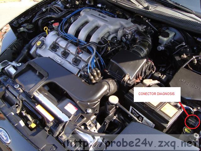 |
| Figure 3 |
Once you locate the connector, will open its lid, and through a cable or clip connect pins TEN (top row, 2nd from the right) with GND (2nd row, 1st from left) (Figure 4) |
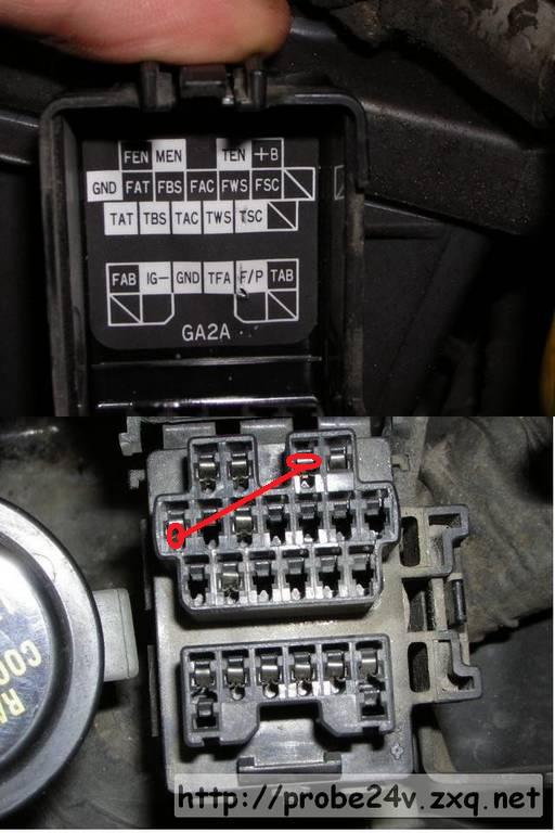 |
| Figure 4 |
When we made the bridge between the pins set, insert the key in the ignition, and we will turn 2 positions (just one before starting the engine). At this point, we are the dashboard lights up in habitual witnesses, including "Check engine". This witness, if the electronic control not detect any errors, or not have any memorized, after a few seconds off. If the control unit detects an error, or errors have memorized, represented by the intermittent witness "Check engine" using the following code: - Long pulses (1.6 seconds lighting) represent tens Thus, for example, 2 long pulses and 3 short pulses represent code 23. When we finish reading the codes, will remove the ignition key and remove the bridge connector diagnosis. To remove the code from memory, simply disconnect the negative terminal of the battery and hold the brake pedal for 20 seconds Below is a list of error codes indicating the sensor or actuator that is affected |
| MOTOR ERROR CODES |
| CODE | CIRCUIT | MEMORIZED |
| 02 | NE2 crankshaft position sensor | YES |
| 03 | G camshaft position sensor | YES |
| 04 | NE1 camshaft/crankshaft position sensor | YES |
| 05 | Knock sensor | YES |
| 08 | Volume Air Flow sensor (VAF) | YES |
| 09 | Coolant temperature sensor (CTS) | YES |
| 10 | Intake air temperature sensor (IAT) | YES |
| 12 | Throttle position sensor (TPS) | YES |
| 14 | Barometric pressure sensor | YES |
| 15 | LHO2S inactivation error | YES |
| 16 | Exhaust gas recirculation (EGR) system | YES |
| 17 | LHO2S inversion error | YES |
| 23 | RHO2S inactivation error | YES |
| 24 | RHO2S inversion error | YES |
| 25 | Fuel pressure regulator control solenoid | NO |
| 26 | Canister purge solenoid | NO |
| 28 | EGR vacuum solenoid | NO |
| 29 | EGR vent solenoid | NO |
| 34 | Idle air control (IAC) solenoid | NO |
| 41 | VRIS #1 solenoid | NO |
| 46 | VRIS #1 solenoid | NO |
| 67 | LFAN relay (1993 only) | NO |
| 69 | ECTF sensor (1993 only) | YES |
This information and more at: http://homepage.ntlworld.com/mx6-uk/maint/maint.htm