


 Brochures
CHECK CONNECTOR
LOCATION |
The diagnostic connector is under the hood near the battery (Figure 1). |
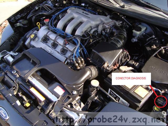 |
| Figure 1 |
DESCRIPTION OF THE PINES |
The following describes the function of each connector pins. (Figure 2 and 3). |
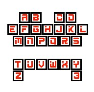 | 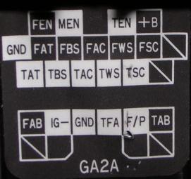 |
| Figure 2 | Figure 3 |
| Pin (Fig.2) | Pin (Fig.3) | Function |
| A | FEN | trouble code output (engine control computer) |
| B | MEN | switch monitor output (engine control computer) |
| C | TEN | diagnostic-mode input (engine control computer) |
| D | +B | switched battery voltage |
| E | GND | ground |
| F | FAT | trouble code output (automatic transmission control computer) |
| G | FBS | trouble code output (anti-lock brakes (ABS) control computer) |
| H | FAC | trouble code output (? not documented for North American vehicles) |
| J | FWS | trouble code output (? not documented for North American vehicles) |
| K | FSC | trouble code output (cruise (speed) control computer) |
| L | - | not used |
| M | TAT | diagnostic-mode input (automatic transmission control computer) |
| N | TBS | diagnostic-mode input (anti-lock brakes (ABS) control computer) |
| P | TAC | diagnostic-mode input (? not documented for North American vehicles) |
| Q | TWS | diagnostic-mode input (? not documented for North American vehicles) |
| R | TSC | diagnostic-mode input (cruise (speed) control computer) |
| S | - | not used |
| T | FAB | trouble code output (air-bag diagnostic monitor computer) |
| U | IG- | igniter coil output (for connection to external tachometer) |
| V | GND | ground |
| W | TFA | diagnostic-mode input (? not documented for North American vehicles) |
| X | F/P | fuel pump relay coil (ground to activate fuel pump) |
| Y | TAB | horn relay |
| Z | - | not used |
| 3 | - | not used |
This information and more at: http://homepage.ntlworld.com/mx6-uk/maint/maint.htm